Peiyuan Pang received his master’s degree from the South China University of Technology in 2021. He is currently a doctoral candidate at the Institute of Applied Physics and Materials Engineering, University of Macau. His research mainly focuses on perovskite electroluminescent devices
Guichuan Xing received his Ph.D. degree in Physics from the National University of Singapore in 2011. He is currently a Professor at the Institute of Applied Physics and Materials Engineering, University of Macau. His major research interests include ultrafast laser spectroscopy, nano optoelectronics, and perovskite for light harvesting and light emission
Metal halide perovskites, as a promising semiconductor material, have been successfully used in electroluminescent devices because of their desirable characteristics, such as good conductivity, high color purity, tunable bandgap, low cost and solution process ability. In the past few years, significant progress has been made in the development of high-efficiency perovskite light-emitting diodes (PeLEDs). These efficient PeLEDs are mainly achieved by sophisticated spin-coating methods, which can easily control the perovskite's composition, film thickness, morphology and crystallinity. However, with the continuous development of PeLEDs, commercial production problems have to be solved, such as large area production, high resolution patterning and substrate diversity, which are difficult for the current spin-coating process.
Graphical Abstract
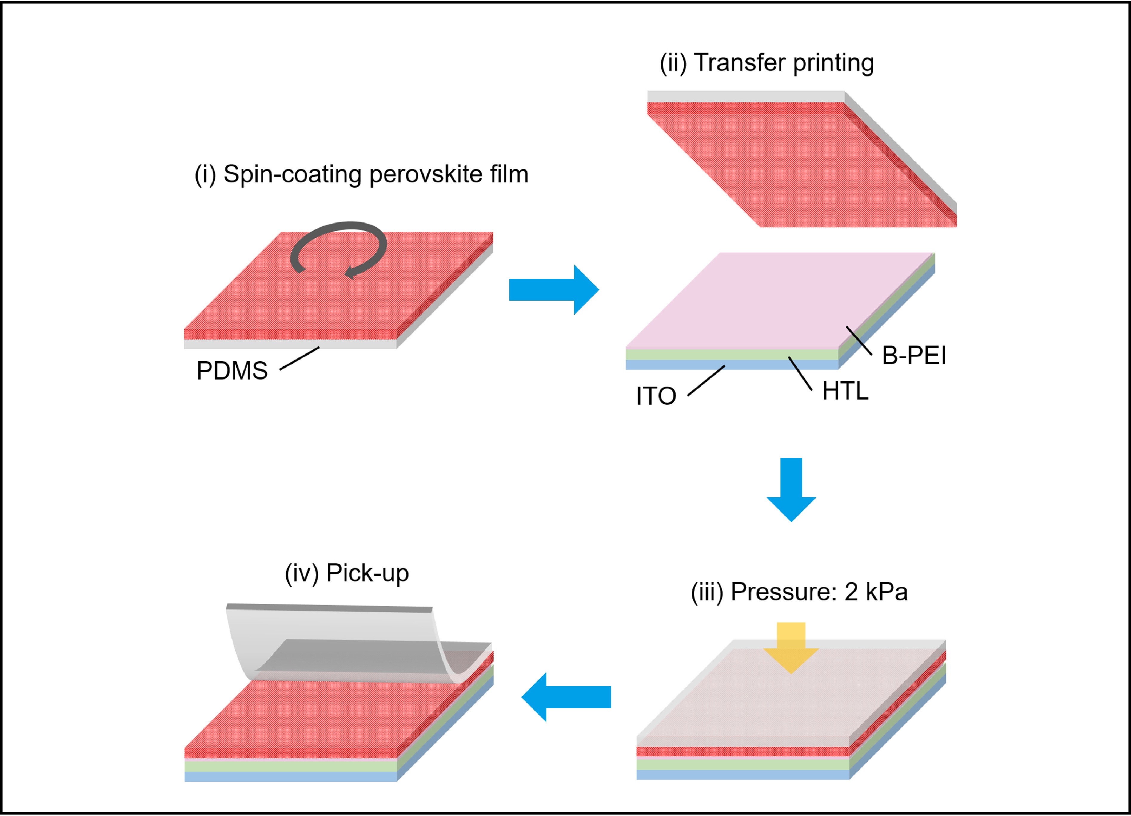
Schematic illustration of the modified transfer printing process.
Abstract
Metal halide perovskites, as a promising semiconductor material, have been successfully used in electroluminescent devices because of their desirable characteristics, such as good conductivity, high color purity, tunable bandgap, low cost and solution process ability. In the past few years, significant progress has been made in the development of high-efficiency perovskite light-emitting diodes (PeLEDs). These efficient PeLEDs are mainly achieved by sophisticated spin-coating methods, which can easily control the perovskite's composition, film thickness, morphology and crystallinity. However, with the continuous development of PeLEDs, commercial production problems have to be solved, such as large area production, high resolution patterning and substrate diversity, which are difficult for the current spin-coating process.
Public Summary
This research highlight summarizes a robust mass transfer printing method for perovskite films fabrication with nanostructures reported by Xiao and colleagues.
This transfer printing method enables the fabrication of large-area perovskite nanostructures with high resolution.
Using this method, white PeLEDs with red and sky-blue emission perovskite micro-stripes has been achieved.
Due to the high theoretical capacity (3860 mA∙h∙g−1) and low redox potential (−3.04 V, vs standard hydrogen electrode, SHE), Lithium (Li) metal is considered an ideal anode material for high energy density batteries[1, 2]. However, the stable plating/stripping of Li metal tends to be impeded by side reactions between Li metal and electrolyte, and lithium dendrites grow uncontrollably, which leads to low Coulombic efficiency (CE), poor cycling stability, and heavy safety risks[3-6]. In practical lithium metal batteries (LMBs), the solid electrolyte interphase (SEI) is of vital importance to avoid the continuous side reactions between the Li metal and electrolyte and thus regulate the nucleation and uniform deposition of lithium metal[7]. Nevertheless, the naturally formed SEI with an inhomogeneous composition on the Li metal surface is mechanically fragile and results in continuous fracture and recombination under large volume changes, which lead to a nonuniform SEI structure[8]. Furthermore, the nonuniform SEI induces lithium dendrite growth during the Li deposition process, which further leads to SEI cracking and accelerates electrolyte consumption. During the subsequent Li-stripping process, parts of the lithium dendrites may be disconnected from the electrode, resulting in dead lithium, which also causes the depletion of fresh lithium by side reactions with the electrolyte. Therefore, stabilizing the SEI structure and regulating the Li-ion distribution on the lithium surface are important to improve the cycling stability of Li metal anodes.
The growth of dendritic lithium will not only accelerate the consumption of active materials but also increase the risk of short circuits, greatly shortening the life span of the battery[9]. To date, great efforts have been devoted to modifying or replacing electrolyte-derived SEIs, including adjusting electrolyte components[10], developing high-modulus solid-state electrolytes[11], and designing artificial protective layers (e.g., two-dimensional materials and polymers)[12]. To alleviate the problems mentioned above, one strategy is to introduce an artificial protective layer onto the lithium metal anode, regulating the migration behavior and distribution of Li ions. Practically, as the uneven flux of solvated Li ions reaches the lithium metal surface, it is rather important to regulate Li-ion migration by hindering the migration of anions and preventing the solvent sheath from contacting the lithium metal anode[13], which is a fundamental way to suppress dendritic lithium growth and prolong the battery life span. Herein, we introduce a black phosphorus-graphite hybrid as a Li-ion regulator enabling stable lithium deposition.
Black phosphorus (BP) is composed of phosphorene layers stacked in puckered subplanes through the weak interactions of van der Waals force[14]. The crystal lattice of BP is composed of diatomic layers, and each layer is composed of a tortuous chain of phosphorus (P) atoms. BP is a semiconductor with a density of 2.70 g∙cm−³ and a Mons’ hardness scale of 2. Moreover, the diffusion coefficient of Li ions within a phosphorene monolayer in the zigzag direction is estimated to be ~100 times faster than that of the graphene layer at room temperature[15]. The mixture of BP and graphite (G) was ball milled to fabricate a hybrid of black phosphorus-graphite (BP-G). Due to the affinity and diffusion ability of black phosphorus for Li ions and the high electronic conductivity introduced by graphite, the artificial protective layer of the BP-G hybrid can induce uniform deposition of Li ions on the Li metal surface and increase the transference number for Li ions at the same time, reducing the side reactions of anions and solvent molecules with lithium metal. With the BP-G Li-ion regulator, the Coulombic efficiency and cycling life of the lithium metal anode can be greatly improved.
2.
Experimental
2.1
Materials and characterization
For battery tests, 1.0 mol∙L−1 Li bis(trifluoromethane-sulfonyl)imide (LiTFSI) dissolved in 1,3-dioxolane/1,2-dimethoxyethane (DOL/DME, 1∶1 in volume) with 2.0 wt% lithium nitrate (LiNO3) additive was used as the electrolyte. Bulk BP was synthesized from red phosphorus by the chemical vapor transport (CVT) method and further exfoliated into few-layer BP flakes. The BP-G hybrid was fabricated by ball milling a mixture of few-layer BP flakes and commercial graphite at a mass ratio of 1∶1.
The structure of the BP-G hybrid was examined by Raman spectra, which were recorded at room temperature with a 532 nm excitation laser. Transmission electron microscopy (TEM, JEM-2100F), high-resolution transmission electron microscopy (HRTEM) images and elemental mappings were acquired to observe the morphology, lattice structure and composition of the BP-G hybrid. The morphologies of the bare Li and (BP-G)/Li metal were characterized by scanning electron microscopy (SEM, Gemini SEM 500 instrument).
2.2
Preparation of (BP-G)/Li metal anodes
The hybrid of BP-G was first dispersed in N-methyl-2-pyrrolidone (NMP) solvent at a concentration of 1 mg∙mL−1, and then the dispersion was stirred for 30 min in an argon-filled glove box before uniformly coating the surface of Li foils with a certain amount of BP-G. The modified Li foils were then dried naturally in a glove box to obtain the (BP-G)/Li metal anodes.
2.3
Electrochemical measurements
The cathodes were prepared by mixing commercial LiFePO4 (LFP) powder with Ketjen black and PVDF at a mass ratio of 84∶8∶8, and then the slurry was cast onto aluminum (Al) foil by a doctor blade. The mass loading of LFP is 4.5 mg∙cm−2, and the thickness of the Li metal foil is approximately 60 μm. For each coin cell, 30 μL electrolyte was added for electrochemical tests. The galvanostatic charge/discharge tests and short circuit tests were conducted by a Land battery test system. Electrochemical impedance spectroscopy (EIS) measurements (0.1–1×10⁵ Hz) and Tafel curves were conducted on Princeton Applied Research analytical equipment.
2.4
Li-ion transference number measurements
The Li-ion transference number (t) was measured in the Li||Li symmetric cells following a previously reported method. The value of t was obtained by EIS (0.1–1×10⁵ Hz, amplitude of 10 mV) before (R0) and after (Rs) direct current polarization with a constant voltage of 5 mV (ΔV). The polarization process took over 1×10⁴ s to reach a steady state, and the current values at the initial (I0) and steady states (Is) were recorded. The transference number was then calculated by the following equation:
t=Is(ΔV−I0R0)I0(ΔV−IsRs).
(1)
The EIS results were fitted according to the equivalent circuit below by ZSimpWin software.
Specifically, R1 and R2 represent the interface resistances (Rct) in Li||Li symmetric cells, and R3 represents the bulk resistance. Q1 and Q2 represent the constant phase elements.
3.
Results and discussion
3.1
Structure of the BP-G hybrid
The Raman spectrum shows three intense bands of the A1g, B2g, and A2g vibration modes of BP at 363, 440, and 467 cm−1, respectively (Fig. 1a). The Raman bands at 1330 and 1590 cm−1 are attributed to the D and G bands of graphite, respectively[16]. The micromorphology of BP-G was characterized by transmission electron microscopy (TEM), and the TEM image of the hybrid shows the particle morphology of BP-G (Fig. 1b). Moreover, the high-resolution transmission electron microscopy (HRTEM) image shows a detailed view of the edge of graphite, and a lattice spacing of 3.4 Å can be measured, corresponding to the d-spacing across the basal planes of graphite. The lattice fringes with a d-spacing of 4.2 Å can be ascribed to the (100) lattice plane of the BP crystal (Fig. 1c). Furthermore, TEM elemental mappings show that P and C are uniformly distributed in the BP-G particle (Fig. 1d–f). These results indicate that the intrinsic structures of BP and G are well preserved in the BP-G hybrid, and these two elements are also well mixed and uniformly dispersed after ball milling.
Figure
1.
Structure characterization. (a) Raman spectra, (b) TEM, and (c) HRTEM images of the BP-G hybrid. (d–f) TEM elemental mapping images of the BP-G hybrid. SEM images of the (g) (BP-G)/Li surface, (h) bare Li metal, and (i) cross section of (BP-G)/Li.
Subsequently, the BP-G hybrid is uniformly modified to the surface of the bare Li foil to form an artificial protective layer. Under scanning electron microscope (SEM) observation, (BP-G)/Li foil shows a smooth surface (Fig. 1g), which is similar to the bare Li foil (Fig. 1h), suggesting that BP-G can be coated on Li foil uniformly. In addition, the cross-section image of (BP-G)/Li foil was also acquired by SEM, showing that the BP-G layer fits tightly on the surface of Li foil with a thickness of 5 μm. Therefore, the BP-G protective layer was successfully introduced to the surface of the lithium metal anode, accompanied by a uniformly flat surface and a suitable thickness.
3.2
Li-ion transport
To our knowledge, solvated Li ions with an uneven concentration distribution reaching the Li metal surface are the main cause for the growth of Li dendrites[17]. Moreover, the transportation of Li ions in the electrolyte and SEI, which is much slower than the transportation of electrons in the electrodes, is usually the rate-determining step of lithium deposition. Therefore, regulating the migration of Li ions reaching the lithium metal surface is an effective strategy to suppress the growth of Li dendrites and prolong the battery life span[18]. Generally, the transportation behaviors of Li ions were studied by Li||Li symmetric cells and Li||Cu half cells, which consisted of Li metal foils as the working electrodes with or without a BP-G protective layer.
To validate the interface charge transfer advantage with the BP-G Li-ion regulator, Tafel curves of the Li||Li symmetric cells were recorded, and the kinetic advantage of (BP-G)/Li foil can be demonstrated by the exchange current density (Fig. 2a)[19]. The higher exchange current density with BP-G (0.64 mA∙cm−2) than the bare Li foil (0.52 mA∙cm−2) enables a faster charge transfer at the interface of the electrolyte and lithium metal anode, which can suppress the parasitic reactions and further provide stable lithium deposition. Likewise, the continuous growth of lithium dendrites, which is mainly caused by the uneven Li metal deposition, would finally lead to the short circuit of the battery, resulting in a sharp voltage drop of the cell[20]. Then, short-circuit tests were performed with Li||Cu half cells, during which the lithium metal was continuously plated on the Cu electrode surface until a short circuit appeared. As shown in Fig. 2b, the cell assembled with the (BP-G)/Li foil can maintain a continuous lithium deposition for over 125 h at a current density of 1.0 mA∙cm−2, whereas the voltage of the cell assembled with a bare Li foil fluctuates and suddenly drops from −55 mV to −4 mV after 78 h, indicating a short circuit of the cell.
Figure
2.
Li-ion transportation behaviors. (a) Tafel curves of the Li||Li symmetric cells with or without the BP-G layer to evaluate the exchange current densities. (b) Short circuit tests of Li||Cu half cells with bare Li or (BP-G)/Li metal anodes at 1.0 mA∙cm−2. Nyquist plots of Li||Li symmetric cells before and after polarization with the (c) bare Li and (d) (BP-G)/Li metal anodes; the corresponding direct current polarization curves of the (e) bare Li and (f) (BP-G)/Li metal anodes.
Furthermore, the Li-ion transference numbers (t) for the modified and bare lithium metal anodes were measured by a direct current polarization method[21]. The transference number is defined as the fraction of the charge carried by a certain species of ion to the total charge in the electrolyte, which is mainly determined by the ion mobility. Electrochemical impedance spectroscopy (EIS) measurements of the cells assembled with (BP-G)/Li and bare Li foils exhibit very close internal resistances (4.2–5.1 Ω), indicating that the introduction of the BP-G protective layer hardly affects the internal resistance of the battery. With the charge transfer resistances (Rct) before and after polarization (Fig. 2c, d) and the polarization current values at the initial and stable states (Fig. 2e, f), the Li-ion transference numbers of the bare Li and (BP-G)/Li anodes can be calculated as 0.37 and 0.62, respectively. The significant improvement in Li-ion transference numbers with the BP-G regulator can be ascribed to the affinity for Li ions and induced deposition by BP. The increased Li-ion transference number is also helpful to exclude the side reactions that involve the anions or the solvent molecules, such as the formation of SEI. Furthermore, since Sand’s time, defined as the time lithium dendrites start to grow, is inversely proportional to the square of the anionic mobility, the increased Li-ion transference number accompanied by a decreased anionic mobility can lead to a larger Sand’s time, rendering the stable deposition of lithium metal anodes. These results proved that the BP-G protective layer can act as a Li-ion regulator, enabling stable lithium deposition.
3.3
Electrochemical performance
To measure the improvement of Coulombic efficiency and long-term cycling performance with a BP-G protective layer, the applications of the (BP-G)/Li and bare Li metal anodes were investigated by Li||Cu half cells, Li||Li symmetrical cells, and LFP||Li full cells.
For a lithium metal battery, CE shows the amount of irreversible consumption of lithium metal during the repeated cycles due to the formation of SEI films and dead Li. Hence, the quite low Coulombic efficiency of the bare Li metal anodes will directly affect the cycling life span of a practical battery[22]. To measure the values of CE, a fixed amount of lithium metal is electroplated on a copper foil during cycling, and then the plated lithium metal is stripped back to the lithium metal anode. Coulombic efficiency is defined as the ratio of the stripped and plated lithium metal. The BP-G-modified Li metal anode exhibits a more stable cycling performance with enhanced CE and prolonged cycling life in an ether-based DOL/DME electrolyte than those with bare Li metal (Fig. 3a). The cell with the BP-G protective layer has a high CE above 98.5% for over 500 cycles. The low CE for the initial several cycles can be ascribed to the side reactions between lithium metal and BP-G or electrolyte, such as the formation of SEI. In comparison, although the CE of a bare Li metal anode can remain quite high compared to that of the (BP-G)/Li anode in the first 100 cycles, it starts to decline and fluctuate rapidly, indicating that the consumption of lithium metal resulted from the electrolyte depletion and growth of dendritic Li. The charge/discharge curves at the 50th (Fig. 3b) and 100th (Fig. 3c) cycles also exhibit an enhancement in electrochemical deposition with a higher CE and smaller polarization.
Figure
3.
Electrochemical performances of Li||Cu half cells and Li||Li symmetric cells. (a) The variation of CE values in Li||Cu cells with the bare Li or (BP-G)/Li metal anodes at the current density of 1.0 mA∙cm−2 and areal capacity of 1.0 mA∙h∙cm−2. The corresponding charge/discharge curves at the (b) 50th and (c) 100th cycles. (d) Voltage profiles of Li||Li symmetric cells with the bare Li (orange line) and (BP-G)/Li (blue line) metal anodes at a current density of 1.0 mA∙cm−2 and an areal capacity of 1.0 mA∙h∙cm−2. The insets show the corresponding enlarged voltage profiles at different cycling stages. Impedance spectra of Li||Li symmetric cells with the bare Li or (BP-G)/Li metal anodes at (e) the initial state and the end of the (f) 100th and (g) 1000th cycles.
The long-term cycling performance was further investigated by Li||Li symmetric cells in a DOL/DME electrolyte. During the cycling tests, Li ions are transported back and forth between the two Li metal electrodes with or without the BP-G protective layer. The current density and areal capacity are set to be 1.0 mA∙cm−2 and 1.0 mA∙h∙cm−2, respectively. The voltage profiles are shown in Fig. 3d. The voltage hysteresis of the Li||Li symmetric cell with the bare Li metal anode (orange line) is initially as large as 100 mV, then gradually decreases within an activation stage, and it suddenly drops from 42 to 20 mV after 190 h of cycling, indicating the short circuit inside the cell resulting from the gradually accumulated dendritic Li. In comparison, the cell with the (BP-G)/Li anode (blue line) renders a constant and stable voltage profile of ~ 50 mV for over 2000 h, which is much more extended to that of the bare Li metal anode, suggesting a uniform and stable lithium deposition interface. In addition, the insets show the corresponding enlarged voltage profiles at different cycling stages, from which it can be seen that the voltage profiles with the BP-G Li-ion regulator show a much more stable plating/stripping voltage than that of the bare Li metal anode.
The electrochemical impedances of Li||Li symmetrical cells from the abovementioned long-term cycling tests were measured at the initial state (Fig. 3e) and the end of the 100th (Fig. 3f) and 1000th (Fig. 3g) cycles. The results were analyzed through equivalent circuit model fitting to provide quantitative information, where the impedance spectra of Li||Li symmetric cells can be decoupled into charge transfer resistances (Rct, interfacial resistance) and bulk resistances (Rbulk, internal resistance). At the initial state, the charge transfer resistance of the (BP-G)/Li anode is much lower than that of the bare Li metal anode (4.8 Ω vs 14.9 Ω), indicating a smaller barrier for the electroplating of Li ions. In addition, the bulk resistances with the BP-G Li-ion regulator are also more stable, with fitted Rbulk values ranging from 5.2 Ω at the initial state to 8.7 Ω after 1000 cycles, suggesting the inhibited growth of lithium dendrites and little electrolyte consumption. However, as the short circuit occurs in the battery, the Rct and Rbulk values of the bare Li metal anode exhibit a sharp decrease after 100 cycles, indicating unstable Li plating and stripping behaviors with the bare Li metal anode.
The electrochemical performances of LFP||Li full cells with the bare Li and (BP-G)/Li anodes were investigated to demonstrate the practical application of the BP-G Li-ion regulator. During cycling, the cell with the (BP-G)/Li anode exhibits a higher specific capacity and an excellent capacity retention compared with that of the bare Li metal anode (Fig. 4a). The initial specific capacity of 162 mA∙h∙g−1 is reached at 1.0 C with a BP-G Li-ion regulator, which maintains excellent cycling performance of 81% capacity retention (131 mA∙h∙g−1) until the 300th cycle. However, although the initial specific capacity of the bare Li metal anode can reach 161 mA∙h∙g−1, it decays rapidly during cycling, and the Coulombic efficiencies are also greatly reduced after 220 cycles. The charge/discharge curves at the 10th and 300th cycles are recorded and shown in Fig. 4b. The cell with the BP-G Li-ion regulator renders a smaller polarization than that of the bare Li metal, which can be attributed to the reduced formation of Li dendrites and electrolyte consumption. Furthermore, the morphology of lithium metal anodes is regarded as direct evidence of stable deposition[17]. Hence, SEM images of the bare Li and (BP-G)/Li anodes after cycling in LFP||Li full cells were collected for comparison. Obviously, sharp dendrites are observed on the bare Li metal surface accompanying the decreased specific capacity (Fig. 4c). In contrast, a smooth surface of the (BP-G)/Li anode is maintained after cycling (Fig. 4d), proving the inhibited growth of Li dendrites with the BP-G Li-ion regulator. These results further confirmed the stable cycling stability and prolonged cycle life contributed by the BP-G hybrid, which is consistent with the electrochemical performances.
Figure
4.
Electrochemical performances of LFP||Li full cells. (a) Variation in specific capacity retention with cycle numbers at 1.0 C. (b) Charge/discharge voltage profiles of the 10th and 300th cycles. Morphologies of lithium metal anodes after 300 cycles with the (c) bare Li or (d) (BP-G)/Li metal anodes.
In conclusion, the hybrid of BP-G can act as a Li-ion regulator, rendering stable lithium deposition by enhancing the Li-ion transference number and alleviating the deposition barrier for Li-ions, resulting from the uniformly distributed lithophilic sites by BP-G, which facilitate the transport and homogeneous dispersion of Li-ions. Therefore, the deposition of Li metal in the cell with the (BP-G)/Li anode is dense and smooth. As a consequence of the multiple beneficial properties of the BP-G protective layer, the suppressed growth of Li dendrites and dead Li on the anode enables a remarkable enhancement in the utilization of Li metal (CE > 98.5% for over 500 cycles), life span (> 2000 h), and low voltage hysteresis (~ 50 mV). Furthermore, the LFP||Li full cell with a BP-G Li-ion regulator offers a high specific capacity (162 mA∙h∙g−1 with 81% capacity retention until the 300th cycle). Therefore, the BP-G Li-ion regulator substantially improves the performance of Li metal anodes, enabling an advanced design strategy for advanced lithium metal batteries with high energy density.
Conflict of interest
The authors declare that they have no conflict of interest.
Acknowledgements
This work was supported by the Science and Technology Development Fund, Macao SAR (FDCT-0044/2020/A1, 0082/2021/A2), UM’s research fund (MYRG2020-00151-IAPME), the National Natural Science Foundation of China (61935017, 62175268) and Shenzhen-Hong Kong-Macao Science and Technology Innovation Project (Category C) (SGDX2020110309360100).
Conflict of interest
The authors declare that they have no conflict of interest.
This research highlight summarizes a robust mass transfer printing method for perovskite films fabrication with nanostructures reported by Xiao and colleagues.
This transfer printing method enables the fabrication of large-area perovskite nanostructures with high resolution.
Using this method, white PeLEDs with red and sky-blue emission perovskite micro-stripes has been achieved.
Xia B, Tu M, Pradhan B, et al. Flexible metal halide perovskite photodetector arrays via photolithography and dry lift-off patterning. Advanced Engineering Materials,2022, 24: 2100930. DOI: 10.1002/adem.202100930
[2]
Zou C, Chang C, Sun D, et al. Photolithographic patterning of perovskite thin films for multicolor display applications. Nano Letters,2020, 20: 3710–3717. DOI: 10.1021/acs.nanolett.0c00701
[3]
Wei C, Su W, Li J, et al. A universal ternary-solvent-ink strategy toward efficient inkjet-printed perovskite quantum dot light-emitting diodes. Advanced Materials,2022, 34: 2107798. DOI: 10.1002/adma.202107798
[4]
Minemawari H, Yamada T, Matsui H, et al. Inkjet printing of single-crystal films. Nature,2011, 475: 364–367. DOI: 10.1038/nature10313
[5]
Du P, Li J, Wang L, et al. Efficient and large-area all vacuum-deposited perovskite light-emitting diodes via spatial confinement. Nature Communications,2021, 12: 4751. DOI: 10.1038/s41467-021-25093-6
[6]
Ávila J, Momblona C, Boix P P, et al. Vapor-deposited perovskites: The route to high-performance solar cell production. Joule,2017, 1: 431–442. DOI: 10.1016/j.joule.2017.07.014
[7]
Carlson A, Bowen A M, Huang Y, et al. Transfer printing techniques for materials assembly and micro/nanodevice fabrication. Advanced Materials,2012, 24: 5284–5318. DOI: 10.1002/adma.201201386
[8]
Linghu C, Zhang S, Wang C, et al. Transfer printing techniques for flexible and stretchable inorganic electronics. npj Flexible Electronics,2018, 2: 26. DOI: 10.1038/s41528-018-0037-x
[9]
Li Z, Chu S, Zhang Y, et al. Mass transfer printing of metal-halide perovskite films and nanostructures. Advanced Materials,2022, 34: 2203529. DOI: 10.1002/adma.202203529
[10]
Kim T H, Cho K S, Lee E K, et al. Full-colour quantum dot displays fabricated by transfer printing. Nature Photonics,2011, 5: 176–182. DOI: 10.1038/nphoton.2011.12
[11]
Kim T H, Chung D Y, Ku J, et al. Heterogeneous stacking of nanodot monolayers by dry pick-and-place transfer and its applications in quantum dot light-emitting diodes. Nature Communications,2013, 4: 2637. DOI: 10.1038/ncomms3637
[12]
Meitl M A, Zhu Z T, Kumar V, et al. Transfer printing by kinetic control of adhesion to an elastomeric stamp. Nature Materials,2006, 5: 33–38. DOI: 10.1038/nmat1532
[13]
Choi M K, Yang J, Kang K, et al. Wearable red–green–blue quantum dot light-emitting diode array using high-resolution intaglio transfer printing. Nature Communications,2015, 6: 7149. DOI: 10.1038/ncomms8149
[14]
Jeong J W, Yang S R, Hur Y H, et al. High-resolution nanotransfer printing applicable to diverse surfaces via interface-targeted adhesion switching. Nature Communications,2014, 5: 5387. DOI: 10.1038/ncomms6387
Figure
1.
Schematic illustration of the mass robust transfer printing process.
References
[1]
Xia B, Tu M, Pradhan B, et al. Flexible metal halide perovskite photodetector arrays via photolithography and dry lift-off patterning. Advanced Engineering Materials,2022, 24: 2100930. DOI: 10.1002/adem.202100930
[2]
Zou C, Chang C, Sun D, et al. Photolithographic patterning of perovskite thin films for multicolor display applications. Nano Letters,2020, 20: 3710–3717. DOI: 10.1021/acs.nanolett.0c00701
[3]
Wei C, Su W, Li J, et al. A universal ternary-solvent-ink strategy toward efficient inkjet-printed perovskite quantum dot light-emitting diodes. Advanced Materials,2022, 34: 2107798. DOI: 10.1002/adma.202107798
[4]
Minemawari H, Yamada T, Matsui H, et al. Inkjet printing of single-crystal films. Nature,2011, 475: 364–367. DOI: 10.1038/nature10313
[5]
Du P, Li J, Wang L, et al. Efficient and large-area all vacuum-deposited perovskite light-emitting diodes via spatial confinement. Nature Communications,2021, 12: 4751. DOI: 10.1038/s41467-021-25093-6
[6]
Ávila J, Momblona C, Boix P P, et al. Vapor-deposited perovskites: The route to high-performance solar cell production. Joule,2017, 1: 431–442. DOI: 10.1016/j.joule.2017.07.014
[7]
Carlson A, Bowen A M, Huang Y, et al. Transfer printing techniques for materials assembly and micro/nanodevice fabrication. Advanced Materials,2012, 24: 5284–5318. DOI: 10.1002/adma.201201386
[8]
Linghu C, Zhang S, Wang C, et al. Transfer printing techniques for flexible and stretchable inorganic electronics. npj Flexible Electronics,2018, 2: 26. DOI: 10.1038/s41528-018-0037-x
[9]
Li Z, Chu S, Zhang Y, et al. Mass transfer printing of metal-halide perovskite films and nanostructures. Advanced Materials,2022, 34: 2203529. DOI: 10.1002/adma.202203529
[10]
Kim T H, Cho K S, Lee E K, et al. Full-colour quantum dot displays fabricated by transfer printing. Nature Photonics,2011, 5: 176–182. DOI: 10.1038/nphoton.2011.12
[11]
Kim T H, Chung D Y, Ku J, et al. Heterogeneous stacking of nanodot monolayers by dry pick-and-place transfer and its applications in quantum dot light-emitting diodes. Nature Communications,2013, 4: 2637. DOI: 10.1038/ncomms3637
[12]
Meitl M A, Zhu Z T, Kumar V, et al. Transfer printing by kinetic control of adhesion to an elastomeric stamp. Nature Materials,2006, 5: 33–38. DOI: 10.1038/nmat1532
[13]
Choi M K, Yang J, Kang K, et al. Wearable red–green–blue quantum dot light-emitting diode array using high-resolution intaglio transfer printing. Nature Communications,2015, 6: 7149. DOI: 10.1038/ncomms8149
[14]
Jeong J W, Yang S R, Hur Y H, et al. High-resolution nanotransfer printing applicable to diverse surfaces via interface-targeted adhesion switching. Nature Communications,2014, 5: 5387. DOI: 10.1038/ncomms6387


 DownLoad: